Nested cluster diagram
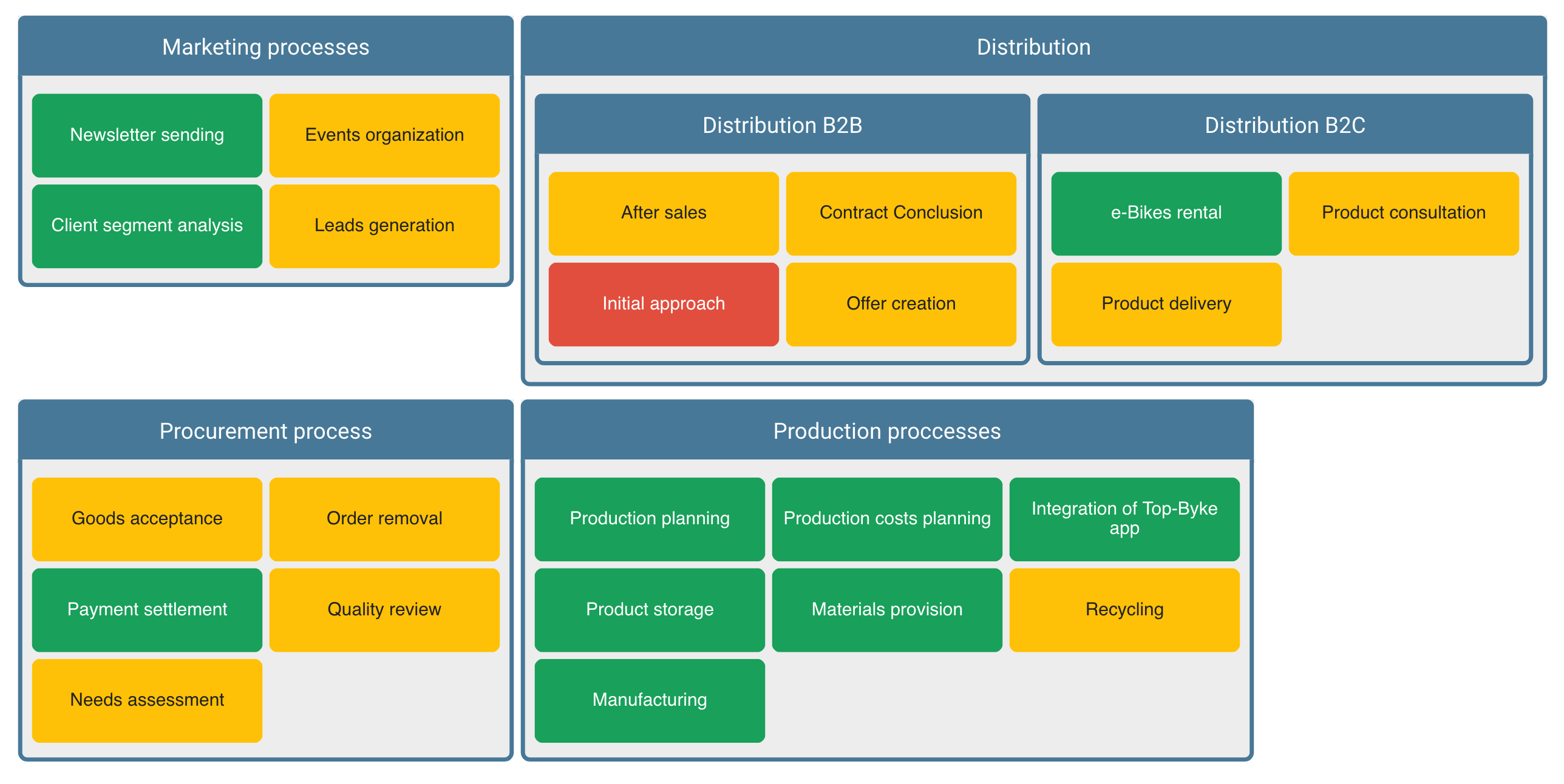
Visualize building blocks and their attributes as nested boxes using the nested cluster diagram. This visualization allows you to specify an outer and inner type and is convenient for displaying one-to-many relationships as well as hierarchies.
Please note that the nested cluster diagram only supports up to three hierarchical levels in the outer layer. Everything on a lower hierarchy level will not be shown.
Example use case
Visualize information systems with supporting capabilities within the organization and understand their technical state of health in order to predict upcoming problems.

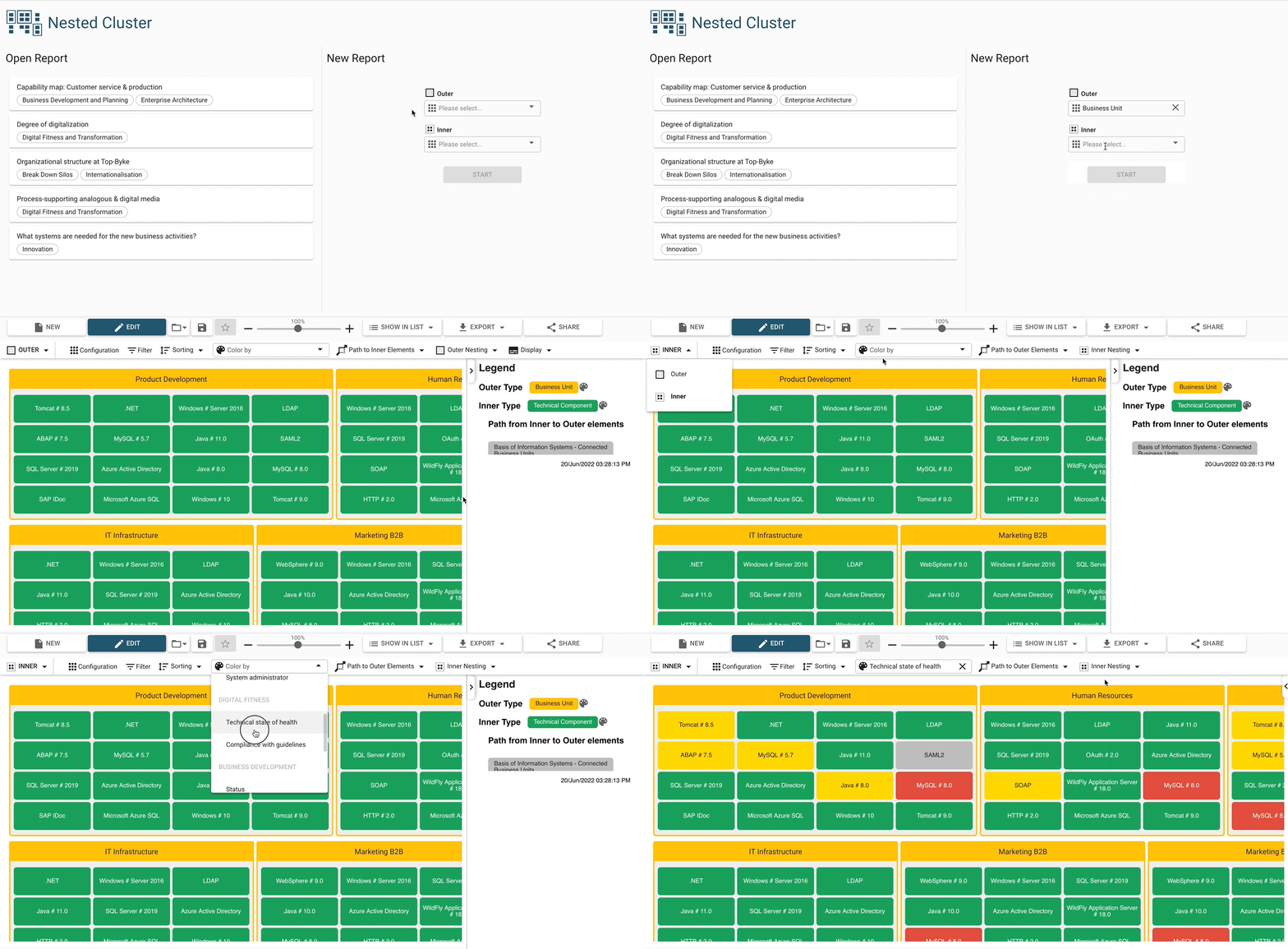
Configuring an inner and outer type
Start by selecting an outer type, which can either be a building block type or an attribute. The selection of the outer type determines which inner type can be chosen, as it needs to be connected to the outer type either via relation (also supports indirect relations) or attribute availability. The diagram will then visualize both types as nested boxes stacked into each other.
The diagram can be further customized by both inner and outer type with filtering, sorting, and coloring.

Specifying the connecting path
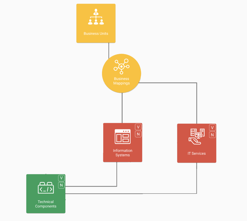
The nested cluster supports indirect relations between building blocks of outer and inner type. This means two types can be visualized that are only connected through another type in between. There is usually more than one possible indirect relation, a so-called connecting path. The diagram chooses one of them by default, or one can be specified in the “path to elements” dropdown.
Example use case
Visualizing all technical components which are used in certain business units. In the meta model, technical components are connected to business units indirectly either via information systems or via IT services. Depending on your use case, you might want to visualize either one of the two.

Sometimes there are multiple connecting paths. It is possible to choose which of the two paths (indirect relations) to visualize.
Additional nesting for self-relations
In the nested cluster you can add an additional outer and inner nesting. This additional nesting only supports the very same building block type and it is possible to choose which self-relation should be used to determine the displayed elements.
Example use case
This setting is particularly useful for visualizing building block hierarchies. Additional child or parent elements through more layers of nesting can be displayed, by choosing the appropriate self-relation related to hierarchy (for example, by “subordinate business unit”).
Additional display options
Orphaned elements (for outer type): by default, outer elements which don’t have connected inner elements are hidden. Use this setting to display those elements.
